Securing a transmission component such as a belt pulley to a drive shaft seems like a routine task, but engineers and mechanics can easily overlook some of the selection and installation factors required to achieve a good connection.
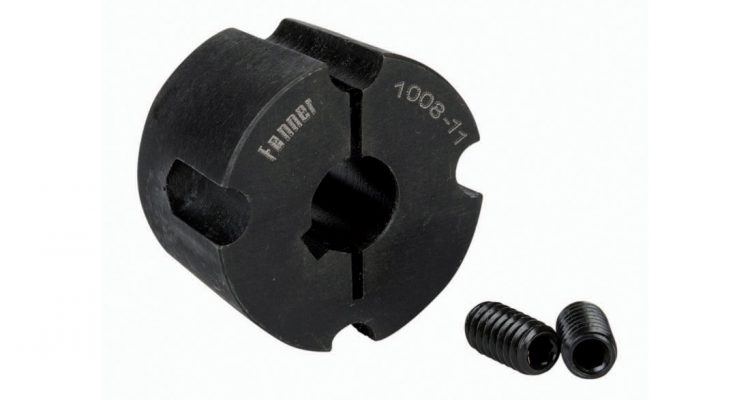
Keyed tapered bushings are among the most common devices used to attach pulleys to shafts. Fenner, a worldwide leader in mechanical power transmission and motion control solutions, offers a comprehensive line of both keyed and keyless locking devices. The Fenner
Taper-Lock® system has been a predominant method of fixing transmission components to machine shafts for over
60 years.
BSC Product Manager Troy Markland says the Fenner Taper-Lock system is particularly popular where time is a critical factor for installation and removal.
“We usually recommend Fenner Taper-Lock bushings where ease of installation and removal is critical to reducing downtime. These bushings are extensively used in applications such as HVAC (heating, ventilation, and air conditioning) systems, industrial pumps and roller chains and sprockets,” says Troy.
But successful operation of assemblies depends upon following the fitting instructions carefully. If the bushings are fitted incorrectly, the drive system may encounter efficiency issues, such as pulley wobbling as well as fretting corrosions on the shaft.
Though seemingly simple, Troy says one of the most common mistakes when installing Taper-Lock bushes is not using the recommended torque settings to tighten the screws.
Hole alignment is another key factor to keep in mind for quick installation, according to Troy.
“The four-hole design of the Fenner Taper-Lock helps in maintaining the balance during assembly process. Fenner also provides its bushes in a full range of metric and imperial sizes, so there is no need for re-boring.”
Fenner Taper-Lock® Installation Instructions:
1. After ensuring that the mating tapered surfaces, bore and shaft are completely clean and free from oil or dirt, insert the bush in the hub so that the holes line up.
2. Sparingly oil thread and point of grub screws, or thread and under head of cap screws. Place screws loosely in holes threaded in hub.
3. If a key is to be fitted, place it in the shaft keyway before fitting the bush. It is essential that it is a parallel key and side fitting only and has top clearance.
4. Clean the shaft and fit the hub to shaft as one unit and locate it in the desired position, remembering that the bush will nip the shaft first and then the hub will be slightly drawn on to the bush.
5. Using a hexagon wrench tighten the screws gradually and alternately to torque shown in table below.
6. Lightly tap using hammer against the large end of bush, using a block or sleeve to prevent damage. Screws will now turn a little more. Repeat this alternate hammering and screw tightening once or twice to achieve maximum grip on the shaft.
7. After the drive has been running under load for a short time, stop and check tightness of screws.
8. Fill empty holes with grease to exclude dirt.
To remove:
1. Slacken all screws by several turns, remove one or two according to number of removal holes. Insert screws into removal holes after oiling thread and under the head of cap screws.
2. Tighten the screws alternately until the bush is loosened in the hub and assembly is free on the shaft.
3. Remove assembly from shaft.
| Bush size | 1008 | 1108 | 1210 | 1610 | 1615 | 2012 | 2517 | 3020 | 3030 | 3525 | 3535 | 4030 | 4040 | 4535 | 4545 | 5040 | 5050 | |
| Screw tightening torque (Nm) | 5.6 | 5.6 | 20 | 20 | 20 | 30 | 50 | 90 | 90 | 115 | 115 | 170 | 170 | 190 | 190 | 270 | 270 | |
| QTY | 2 | 2 | 2 | 2 | 2 | 2 | 2 | 2 | 2 | 3 | 3 | 3 | 3 | 3 | 3 | 3 | 3 | |
| Screw details | Size (BSW) | 1/4” | 1/4” | 3/8” | 3/8” | 3/8” | 7/16” | 1/2” | 5/8” | 5/8” | 1/2” | 1/2” | 5/8” | 5/8” | 3/4” | 3/4” | 7/8” | 7/8” |
| Hex. socket size (mm) | 3 | 3 | 5 | 5 | 5 | 6 | 6 | 8 | 8 | 10 | 10 | 12 | 12 | 14 | 14 | 14 | 14 | |
| Large end dia. (mm) | 35.0 | 38.0 | 47.5 | 57.0 | 57.0 | 70.0 | 85.5 | 108.6 | 108 | 127 | 127 | 146 | 146 | 162 | 162 | 178 | 178 | |
| Bush length (mm) | 22.3 | 22.3 | 25.4 | 25.4 | 38.1 | 31.8 | 44.5 | 50.8 | 76.2 | 63.5 | 89.0 | 76.2 | 102 | 89.0 | 114 | 102 | 127 | |
| Approx mass (kg) | 0.1 | 0.1 | 0.2 | 0.3 | 0.5 | 0.7 | 1.5 | 2.7 | 3.6 | 3.8 | 5.0 | 5.6 | 7.7 | 7.5 | 10.0 | 11.1 | 14.0 |